


This page last modified 2013 October 28
A Hand-Driven Scotch Mount
What is a Scotch Mount?
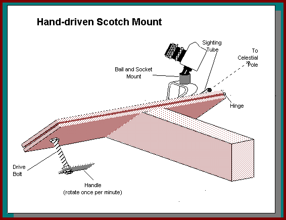
A Scotch mount, aka Barn-door drive (after its appearance) or Haig mount (after its inventor) is a simple device for tracking the motion of stars across the heavens for, e.g. astrophotography.
The stars appear to rotate around the celestial pole at a rate of 15° per hour, the sidereal rate. If we wish to take photographs of the night sky without having the images trail, the camera must track the sky at the sidereal rate, unless exposures are to be limited to a few seconds. We achieve this tracking with a camera drive, of which there are many available types. This one, which is essentially two planks of wood, hinged together and driven by a piece of threaded rod, permits exposures of up to 10 minutes to be made with a 50mm lens, revealing some of the fainter wonders of the heavens. It can be made in an afternoon with simple components and tools, and minimal workshop skills.
Materials
These materials are what I used. Use what you have readily/cheaply available and adapt the design to suit. There is a paragraph on Scotch Mount Mathematics if you wish to calculate the board dimensions for use with a different sized threaded rod. I have given metric measurements with approximate "sensible" Imperial equivalents where appropriate.
| Quantity | Description | |
| Approx. 0.75m (30") | 115mm x 20mm (4½" x ¾") MDF, plywood or timber | |
| Approx. 0.25m (10") | 90mm x 40mm (3½" x 1½") timber | |
| Approx. 70mm (3") | 20mm x 7mm (¾" x ¼")timber | |
| 10cm | M10 threaded rod | |
| 4 off | M10 hexagonal nuts | |
| 2 off | M10 washers | |
| 1 off | 100mm (4") hinge, of stout construction | |
| 1 off | ¼-inch x 20tpi bolt (¼-inch UNC) | |
| 1 off | Ball-and-socket mount for camera | |
| Approx. 11cm (4½") | 15mm copper pipe | |
| Approx. 40cm (1½") | 20mm x 3mm aluminium | |
| Approx. 20cm (8") | Wire (approx. 22 swg) | |
| Assorted screws | ||
| Silicone adhesive (or RTV) |
Construction
Boards
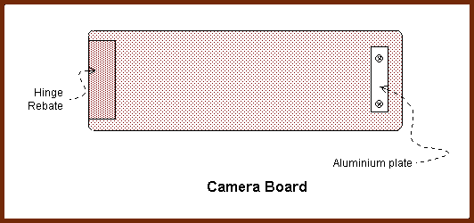
- Cut two 360mm lengths from the 115mm x 20mm board. Select one to be the base board and one to be the camera board.
- Mark a line along the centre of the long length of the base board.
- Rebate both boards for the hinge and screw the hinge to the base board.
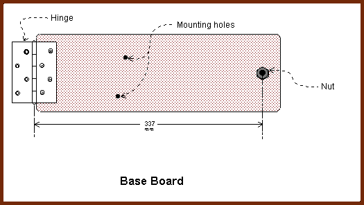
- Mark the line exactly 337mm from the centre-line (axis) of the hinge-pin.
- Drill a 4mm pilot hole at this mark, then enlarge the hole to 10mm.
- Position the camera board on the hinge (do not screw it yet) and mark the position of the 10mm hole.
- Cut a 75mm length of aluminium and fix it over this mark.
Drive Bolt
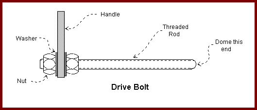
- Cut a 100mm length of the M10 rod and de-burr the ends with a fine file.
- Decide which end of the drive-bolt will bear on the camera board and grind this end to a dome. If you have no grinding wheel. this is easily done by putting the other end of the bolt into the chuck of a drill and running the end to be domed against a file or carborundum stone. It is important that this is done as accurately as possible, with the dome symmetrical about the longitudinal axis of the bolt. Wear safety goggles!
- Cut a 70mm length of the 20mm x 7mm wood. Drill a 10mm hole in one end. This is the handle.
- Place the handle on one end of the bolt and clamp it tightly in between two nuts and washers.
Camera Bracket
- Bend the rest of the aluminium into shape to make the camera bracket.
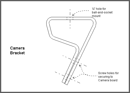
- Drill a ¼-inch hole for the bolt that will secure the ball-and-socket mount.
- Drill the holes for the screws that will secure the bracket to the camera board.
- Bolt the ball-and-socket mount to the camera bracket.
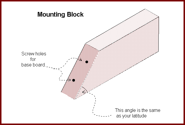
Block
- Use a protractor to mark one end of the 90mm x 40mm block with your latitude.
- Carefully cut the block to this angle.
Assembly
- Drill two clearance holes in the base-board. These should be about 20mm from the edge of the board and about 150mm from the hinge-pin.
- Carefully position the base-board on the angled end of the block and mark the block through the clearance holes.
- Drill pilot holes in the block and screw the base board tightly to the
block.
- Put the drive-bolt through the hole in the base-board and place a nut on the end . Pull the nut tight against the base board and draw around it. Remove the nut and bolt from the base board.
- Repeat (4) to mark the other side of the hole.
- Using a sharp chisel, make 5mm deep recesses for the nuts in the base-board and put the nuts in them.
- Thread the bolt through the nuts and the base-board. Check that the bolt runs freely – you should be able to easily turn it between finger and thumb without using the handle.
- When the bolt runs freely, glue the nuts into place, ensuring that no adhesive gets onto the threads.
- Screw the camera bracket to the camera board.
- Screw the camera board to the hinge.
NB: For southern hemisphere use, reverse the board, so that the hinge is on the left in the diagram above.
Sighting Tube
The sighting tube must be mounted parallel to the hinge-pin.
- On the camera board mark a line parallel to the hinge and file a V-shaped groove.
- Drill two pairs of holes in the camera board to enable the tube to be secured with wire.
- Secure the tube to the board so that it rests in the groove. Ensure that it does not protrude over the edge of the board – this is for the safety of your eye!
- Clamp the mount and sight a distant object through the tube.
- Swing the camera-board through 180° on its hinge. When the object being sighted does not appear to move as the camera board is swung, the tube is parallel to the hinge.
- Put a line of silicone adhesive on either side of the tube. Check that the tube is still aligned, adjust if necessary, and allow the adhesive to set.
Using the Scotch Mount
- The mount must be secured firmly to a stable support, such as a tripod or a table, so that the camera board is free to move and the handle is free to rotate.
- The camera is then attached to the ball-and-socket mount.
- The mount must be aligned to the celestial pole by adjusting the support until the Pole Star, Polaris, is central in the sighting hole. (Although Polaris is not precisely at the celestial pole, it is sufficiently close for this mount.)
- Focus the camera on the desired object and, using a cable-release, open the shutter.
- Rotate the handle at the same speed as the second-hand of a clock or wristwatch.
- After the desired exposure time, close the camera shutter.
- Rewind the mount – its tracking is most accurate when the boards are nearly parallel.
Hint:
To reduce vibration in SLR cameras, it is
good practice to lock up the mirror before opening the shutter. If the camera
does not have a lock-up facility, use the "hat trick". A dark hat (or
similar object) is held over, but not touching, the lens whilst the shutter is
opened. The exposure is begun and ended by removal and replacement of the hat.
Further projects
Sooner or later you may find that you would prefer a more accurate,
motorised drive. This Double-Arm Scotch Mount may be
just what you want.
Scotch Mount Mathematics.
| 1 sidereal day | = 1436 minutes |
| Tracking rate | = 360°/sidereal day |
| = 360/1436°/minute | |
| = 0.25°/minute | |
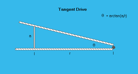
| Pitch of M10 thread | = 0.147mm |
| tanθ | = a/r |
| r | = a/tanθ |
| = 0.147cm / tan 0.25° (for M10 thread) | |
| = 33.7cm |
