


This page last modified 1997 April 29
A Better Barn Door

Contents
- Introduction
- Improving the Basic Design
- Design
- Construction
- Oscillator/Driver
- Polar Alignment
- Performance
- Hardware Requirements
- Electronic Components
- Calculation of Drive Arm Length
- Signal Frequencies on CMOS 4024 pins
Introduction
An inexpensive route to astrophotography has long been the Scotch Mount, also known as the Barn Door Drive (after its appearance) or the Haig Mount (after its inventor). A double-arm mount offers much greater accuracy than conventional designs. In its simplest form, the Scotch mount consists of two boards of wood, hinged at one end and driven near the other by a bolt which passes through the lower board and bears on the upper one.
If it is to be hand-driven, it is conveniently made so that one revolution of the handle is made in one minute so that the handle may be synchronised with the second-hand of a watch. This is the tangent drive configuration.
A tangent drive will be close to sidereal rate for only a very small angle. If carefully made, it will track for 5 to 10 minutes before trailing becomes apparent with a 50mm lens.
Improving the Basic Design
Accuracy of tracking can be improved by building the mount in an isosceles configuration.
The drive is then across a cord of the arc through which the arm is driven and exposures of up to 20 minutes are possible with a 50mm lens. An isosceles drive is much more difficult to build since both ends of the drive bolt must swivel about an axis parallel to the hinge. If this extra effort is to be taken, it makes sense to improve the tracking accuracy even further if this can be simply achieved. Many ways of improving the tracking accuracy have been tried, but the simplest to make with simple tools must be the double-arm configurations investigated by Dave Trott (Sky and Telescope, Feb 1988). The configuration with the greatest potential is Trott's Type 4 configuration, which can provide excellent tracking for nearly an hour, by which time errors resulting from atmospheric refraction would exceed the error of the drive.
In the double-arm mount, the moving arm of the isosceles configuration drives a second arm upon which the camera is mounted. The duration of accurate tracking is determined by the parameter β, which is the ratio b/c. The angle φ through which the camera arm moves is given by :
φ = θ + arcsin(sin θ /β)
where θ is the angle through which the drive-arm moves. Accurate solutions exist when β is in the region of 2.000 to 2.186 (Sky and Telescope, Apr 1989).
Design
The double arm mount shown in the photograph uses a 6mm (M6) threaded rod to drive it. This size was chosen because its thread-pitch of 1mm simplifies calculations. Given a motor drive rotating at 1rpm, a solution of the equation above gives, to the nearest mm, the following dimensions:
r = 333mm
b = 254mm
c = 116mm
However, since the accuracy of the drive depends upon the ratio b/c, it is advantageous to design the mount such that the length of b can be adjusted in the event that errors creep in during actual construction.
The accuracy of tracking will also depend upon an accurately driven motor. It was decided to construct a simple crystal oscillator/driver for a stepper motor. R/C oscillators are less expensive to make, but their accuracy suffers from the disadvantage of being temperature sensitive.
Construction
The mount shown in the photograph has boards of medium density fibreboard (MDF), which is very simple to work using hand-tools. If it is properly sealed with varnish, it does not easily warp and is dimensionally stable compared to most commonly available softwood timber. Constructors who have not previously worked with MDF should note that it is an advantage to countersink any pilot- holes before inserting screws, in order to prevent the material around the hole lifting above the surface of the board. Care should also be taken not to inhale any dust generated from MDF -- all wood-dust is potentially harmful, but the bonding agent used in MDF is also suspected of being toxic if inhaled. Wear a face-mask.
Aluminium angle was cut and drilled to form the motor-mount and gearbox, the latter being necessary because the motor, salvaged from a broken dot-matrix printer, has a step angle of 7.5°. A 5:1 gearbox permits the oscillator/driver circuit to drive the rod at 1rpm. Different motors will, of course, require different gearing or even no gearing at all.
Bushes for the threaded rod were made from cylindrical brass rod-connectors and were pressed, using a vice, into holes in the aluminium. The motor/gearbox assembly was then mounted on the fixed board using a stout brass hinge. All hinges used in this project must be solidly constructed with no play in the joint, which must move freely. Good quality brass hinges usually meet these requirements.
The drive-arm must be drilled to accept a nut assembly which can rotate about an axis parallel to that of the hinges.

This assembly was made by filing six equi-spaced grooves into the inside of a 12mm (M12) nut and using a vice to press a 6mm nut into the larger nut. Opposite flats of the larger nut were drilled to accept 3mm bolts which, having been decapitated, serve as swivels.
A 2.5mm hole is drilled diametrically across the larger, 28mm, hole, parallel to the hinge axis, to accept the swivels. The assembly is inserted into the drive-arm as follows: Firstly, the upper swivel is inserted into its hole in the drive-arm. Then the nut assembly is put into its hole and impaled upon the swivel. Lastly, the outer swivel is inserted and the swivel hole is closed with a metal plate. If the swivels are a tight fit in the holes in the drive-arm, the position of the swivel assembly can be fine-adjusted along its axis by rotating the swivels with a pair of long-nose pliers.
A strip of textured formica (edging-strip for kitchen work-surfaces is suitable) is glued along the drive-arm where the camera arm will bear upon it. The completed drive-arm is then mounted on the fixed board with another hinge, ensuring that the axis of this hinge is parallel to that of the one holding the motor/gearbox and that distance from the hinge axis to the centre of the drive-rod is accurate.
The camera arm is now assembled.
A stout bracket was made of aluminium, to which was attached a ball-and-socket camera mount.
This is screwed to the camera-arm, which is in turn screwed to a third hinge, which is itself screwed to the fixed board, again ensuring that the hinge axis is parallel to those of the other hinges and that it is placed the correct distance, c, from the drive-arm hinge. A piece of teflon must be attached to the camera-arm where it bears upon the formica on the drive- arm. It is as well to re-measure the distance between the drive-arm and camera-arm hinges in order that the teflon can be positioned so that the distance of the bearing surface from the camera-arm hinge axis, b, gives a value for b which is as close as practicable to the optimum value.
The fixed board is now screwed to the frame, cut at the angle of your latitude, which attaches it to the tripod or whatever else will support your mount. The frame is secured to the tripod with a central 10mm bolt. 6mm bolts, which bear on the tripod head, are arranged at 120° intervals around this to allow the mount to be correctly aligned.
The Oscillator/Driver
The drive electronics are based on a circuit published on the World Wide Web by Ray Grover. The output of a 4.194304MHz crystal (X1) is divided by the CMOS chips, 4060 and 4024, to give a 4Hz output to the SAA1027 stepper-motor driver. Each of the stepper-motor (SC1) inputs is connected to an output of the SAA1027.
If you are uncertain of the correct sequence of the stepper-motor input leads, some experimentation will be necessary to establish this -- this will not harm the motor. For more information on stepper motors, visit the excellent Jones on Stepping Motors.
Rewinding the drive-screw is effected by switch S2, which reverses the direction of the stepper- motor by raising the voltage on pin 3 of the SAA1027. It also connects the 64Hz output (pin 11) of the 4024 to the SAA1027 input, giving a rewind rate 16x the drive rate. S3, a normally closed push- button switch mounted on the fixed board, breaks the circuit when the boards come together. The LED flashes when the circuit is powered.
The components can be mounted on a piece of strip-board. The ICs are conveniently (and more safely!) mounted in sockets which are soldered to the strip-board. More flexibility in the use of the strip board is possible if unused pins are removed from the IC sockets before they are soldered to the board. The ICs are inserted into their sockets when soldering is complete. The circuit is put in a project box with flying leads to the motor and switch S3.
The circuit draws about 0.25 amp. It should not be connected to an unregulated supply in case the voltage surges above the safe limit of 15 volts. The diode D1 protects the circuit against accidental reverse-polarity connection. A 12 volt lead-acid battery is a convenient power source and, if the power lead is fitted with the appropriate plug, the circuit can be driven from a car's cigarette-lighter socket.
Polar Alignment
There is little point in making an accurate mount if it cannot be accurately polar-aligned. The polar alignment is effected by a simple "projected pinhole" type finder .

A pinhole was made in a disc of baking foil, which was mounted, in a tube, at the focus of a small biconvex lens. There is no need for an achromatic lens since the LED which illuminates the pinhole is sensibly monochromatic. The lens, therefore, projects the pinhole at infinity. This is checked by testing for parallax between the pinhole and a star when the eye is moved.
If the sky is viewed with both eyes open, one of them looking into the finder, the pinhole is projected onto the background stars. The finder is mounted on the camera arm, conveniently at the end most distant from the hinge. It is adjusted until there is no discernible movement of the pinhole against a distant object when the camera arm is rotated about its hinge -- it is then parallel to the axis of the camera-arm hinge and can be fixed in place. Silicone adhesive is suitable for this purpose.
As the celestial pole is 44 arcmin from the star Polaris (alpha Ursae Minoris), the pinhole can be made larger so that its illuminated disc subtends double this angle, i.e. 1.5°. The pinhole size can be achieved through trial and improvement -- I initially achieved it accidentally and, fortunately, recognised it's usefulness before I discarded the "ruined" pinhole. If the disc is now placed so that it is on the Kochab (β Ursae Minoris) side of Polaris, with Polaris on its rim, polar alignment can be obtained to better than 10 arcmin.
If this is to be done, it is essential to have a method of dimming the LED -- a 5kW potentiometer is suitable, but dimming can just as easily be achieved by covering the eye-end of the finder with a small piece of plastic lens cut from discarded sunglasses.
The error of polar alignment will most likely be the largest error affecting the mount. An alignment error of 10 arcmin will give a tracking error of about 2.5 arcsec per minute.
Performance
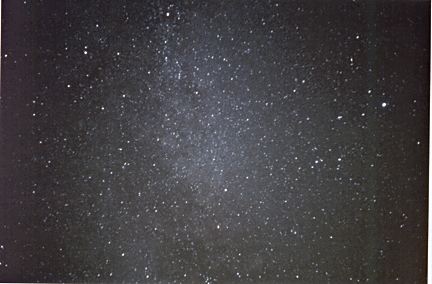
The mount performs very well indeed when properly polar aligned. 25 minute exposures with a 50mm lens show no evidence of trailing when the star images are viewed under a microscope. Longer exposures have not yet been attempted, owing to the light-polluted nature of the local skies. This photograph of the Cygnus/Lyra region is a 15min exposure on Lloyds ISO100 film, 50mm lens at f/2. (It's lost a bit in the scanning).
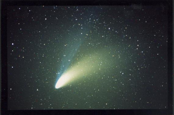
The following image of Comet Hale-Bopp (with M34 in the ion tail) is a 8-minute exposure with a 135mm lens at f/2.8, taken 1997 April 06, on Fujichrome Sensia ISO400.
Whilst it does not afford the potential for guided photography, its performance matches, and possibly exceeds, that of some commercially available camera mounts intended for unguided photography. It does so for a very modest financial outlay at the cost of less than a weekend in the workshop, thereby putting the possibility of high-quality astrophotography within the reach of all.
Hardware requirements
No attempt is made to give a minutely detailed parts list since, in a project like this, both design and construction depend upon the ingenuity of the constructor and the adaptability of available materials.
- Approx1.5m x 100mm x 12mm MDF, plywood or timber (for boards)
- Timber for the rest of the mount
- 3 good quality 75mm hinges
- Ball-and-socket mount for camera
- Approx120mm x 6mm threaded rod
- A stepper motor
- Gears (if necessary, dependant on stepper motor)
- Approx. 200mm Formica edging strip
- 40mm x 6mm x 6mm teflon
- Various nuts; bolts; screws; aluminium strip and angle; brass bushes; as required.
Electronic Components
- ICs
CMOS 4060 divider/oscillator 1
CMOS 4024 divider 1
SAA1027 Stepper motor controller 1 - Crystal
4.194304MHz Quartz crystal 1 (X1) - Diodes
LED, red, miniature 1 (LED1)
1N4003 or similar (200v, 1A) 1 (D1) - Capacitors
100µF 16v electrolytic 1
0.1µF ceramic disc 1
47pF monolithic ceramic 1
100pF monolithic ceramic 1 - Resistors
100W 0.6W 1
220W 1W 1
2k2W 0.6w 1
3k3W 0.6w 1
100kW 0.6w 1
330kW 0.6w 1 - Switches
SPDT toggle, subminiature 1 (S1)
DPDT toggle, subminiature 1 (S2)
Push-to-break button 1 (S3) - Miscellaneous
Plug and socket for power connection
Vero stripboard
Box to house circuit
7/0.2 wire
DIL sockets for ICs
LED clip
Calculation of Drive-Arm Length
If b = 254mm and β = 2.186,

then c = 254/2.186 mm
       = 116.2mm

φ should change at 2π radians per day
      = 360/1436 °/min

Solving φ = θ + arcsin (sinθ / β), we find that
the equation is satisfied when

θ = 0.172° /min.

Pitch, p,  of 6mm thread = 1mm
Stepper motors are commonly available with step angles of 7.5° (48/min) and 1.8° (200/min):
Motor with 7.5° step angle and 4Hz input to SAA1027
Motor turns with a period of 360 / (7.5 x 4) sec
        = 12sec

Using this drive rate will result in very long drive-arm, resulting in
a heavy and unwieldy mount, hence gearing of 5:1 is required to attain
a drive rate of 1 rpm.

θ = 2 arcsin (p/2r), where r is the length of the drive-arm.

  r = 2p/2sinθ
    = 1/sin(0.172° ) mm
    = 333.1mm
Motor with 1.8° step angle and 4Hz input to SAA 1027
Motor turns at a rate of 360 / (1.8 x4) sec
        = 50 sec

This is conveniently close to 1 min, in which time the screw will
advance 60p/50 mm.

θ = 2 arcsin ((60 x p)/(50 x 2r)), where r is the length of the
drive arm.

 r = (2 x 60 x p)/(50 x 2 x sinθ)
    = 6/5sin(0.172° ) mm
    = 399.5mm
Signal Frequency on 4024 pins
| Pin Number | Frequency (Hz) |
| 3 | 2 |
| 4 | 4 |
| 5 | 8 |
| 6 | 16 |
| 13 | 32 |
| 11 | 64 |
| 10 | 128 |
